Hacker Perspective: Thermostat Signals
- The following information is not targeted at the weekend warrior so if you do not have a working knowledge of both "DC theory" and "AC theory", then call a qualified heating-cooling service technician.
- If you run into problems, then you will need to use a DVM (digital voltage meter) to do fault analysis while reading the schematic diagrams specific to your heating-cooling equipment (they are all different) and thermostat (they are all different). If you do not have these skills, or do not own a DVM, or do not have schematic diagrams, then call a qualified heating-cooling service technician.
- If you are not careful with your wiring, or attempt wiring changes with the power turned on, then it is possible that you will damage the PCB (printed circuit board) in your heating-cooling equipment or the associated 24-VAC transformer. In that case you will be calling a qualified heating-cooling service technician to do the repair.
- No warranty of any kind is associated with the information presented below. On top of that, there is no guarantee of any kind as to the accuracy of the information. This page represents one hacker's perspective.
Three basic categories (in this article)
| Thermostat | Smart? | Batteries? | Notes |
|---|---|---|---|
| Mechanical | 0 | n/a | usually can interface with all residential heating-cooling systems |
| Programmable 1 | 1 | Y | 1a) usually interfaces with most older (pre-Y2K) heating-cooling systems 1b) only will interface with heating-cooling systems via a control-line isolation device |
| Programmable 2 | 2 | N | requires a C-wire; often can connecting to your local Wi-Fi hub (when provided) |
Preface
- I've been working in the computer industry for more than 40 years where hardware wiring is documented to the ninth power. Unfortunately, this is not the case in the
heating-cooling business where it appears that every company went their own direction. For example, read the following November-2020 excerpt from the Thermostat article Wikipedia:
"There are no standards for wiring color codes, but convention has settled on the following terminal codes and colors. In all cases, the manufacturer's instructions should be considered definitive".
- I had no experience with thermostat wiring until 1985 when I bought a Honeywell programmable thermostat as a replacement for the mechanical thermostat connected to a mid-efficiency natural-gas furnace in my Canadian house. The instructions back then suggested "taking note of which wire colors were connected to which labeled terminals then just moving the wires to the new thermostat base". A 1-800 telephone number was included that you could call if you got into trouble with an additional suggestion about calling a qualified heat-cooling service technician.
- In the early 1990s I did some consulting work (designing control boards) for a Kitchener-based manufacturer of ground-source heat pumps by the name of Earth Systems. That opportunity allowed me to meet heating-cooling technicians with decades of experience who confirmed my worst fears: no industry standard colors or meanings
- In 1997 I hired a contractor to add air-conditioning (a.k.a. cooling) to my residence, so I was off to a big box store for a better thermostat (IIRC, it was another Honeywell with a larger LCD display). No surprise here: the instructions left much to be desired -AND- the industry still had not moved to any kind of wiring standardization.
- In 2010 I bought a RONA-branded thermostat (RONA is a Canadian big box store) that featured 12 programmable slots (weekdays x 4; Saturday x4; Sunday x 4). The model number was THM303 and appears to have been manufactured somewhere in Asia then imported by UPM Marketing. Still no wiring standardization.
- In 2019 my air-conditioning (a.k.a. cooling) died, and a contractor talked me into also replacing my mid-efficiency furnace with a high-efficiency model (greater than 90%). To get my circa-2010 thermostat working they needed to add an isolation device between the thermostat and furnace. Why? Most battery-powered thermostats are powered by "stealing a tiny amount of power from the signal lines" (the batteries would be dead in 7-10 days if this were not so) but high efficiency furnaces sometimes employ high efficiency control circuits which can no longer tolerate the parasitic powering of the thermostat.
- In 2020 we experienced a residential power outage for a few hours then went shopping. We returned 5 hours later noticing that the inside temperature of our house was
already at 28 C (6 C above the set-point of 22 C). The thermostat clock was frozen at 16:45 which means the CPU (if there was one) had probably been insane for
over 3 hours. I wonder what would have happened if we were on vacation?
- I am a hacker with a background in both computers, electronics, and formal training from Conestoga College. I carefully disassembled this unit to determine where it was manufactured.
- The PCB only contains ENGLISH but has no manufacturer's logo or country of origin. The PCB does contain the iconic backward RU (R connected to U) which is a subset of Underwriters Laboratories. You probably can't sue a cheap manufacturer if you do not know their identity.
- I could not find a CPU or any other chips but there is something under a black glob which appears to also drive the LCD display (this is the usual setup whenever a special purpose silicon chip is manufactured but never installed in plastic or ceramic DIP packaging).
- I replaced this unit with a Honeywell Home RTH9585WF. This unit does not require batteries, but I
did not know that until I attempted to install it when a little page dropped out of the box titled "C-Wire Addendum" and I wondered what is a C
wire? Some sites, like this one at Wikipedia, claim than "C" is
"ground" but that cannot possibly be correct since I opened my furnace then poked around with a DVM only to discover that:
- "RC + RH (which are usually linked together)" float closer to ground, and...
- 24 VAC can be measured between any of the call lines and "RC + RH" when the unit was idle
In the beginning...
In the early days of residential heating (or heating-cooling) system designers went out of their way to keep everyone safe.
- Control systems are usually powered by a 24 VAC transformer rather than line voltage (115 VAC in North America; 230 VAC in Europe)
- BTW, this was sometimes used as a door-bell power supply in most residences.
- Many years ago I worked at a location where the furnace started up every time someone pushed the door-bell-button. Too funny to make up.
- Raw power was never sent through the wires. One side of the transformer output is connected to the control relays while the other side was sent to the thermostat which only needed to close a circuit to, for example, "call for heat".
- Not sending raw power through this circuit will also protect you from blowing a fuse if:
- you wired the thermostat incorrectly.
- you inadvertently shorted the wires by doing an installation with the power TURNED ON
- you inadvertently drove a nail into the thermostat wiring.
- might not cause a short circuit but still could be dangerous by permanently calling for heat - WHICH COULD CAUSE A FIRE
- on some systems it is possible to call for HEAT and call for COOL at the same time. Yikes!
In these instances, any wiring errors could burn out the transformer and/or CAUSE A FIRE
Mechanical 24-volt thermostats
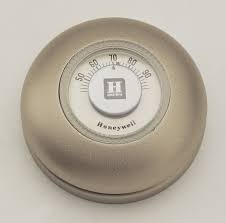
A heating-only Honeywell-T87 is shown to the right (I remember this exact product in my parent's home in the 1950s; notice the Fahrenheit scale). This device works by rotating a coiled bimetallic strip with a mercury bulb attached to the very end.
Overview:
- why bimetallic? Temperature causes different metals to expand (when heated) or contract (when cooled) at different rates. When a coiled spring is constructed of two different metal strips (one each side), differences in length will cause the spring to rotate
- why mercury? a liquid blob of this stuff is used to close an electrical circuit.
- why mercury bulb? When the ball of mercury rolls down the tube, the weight of the mercury will rotate the spring slightly, locking-in the action (avoids electrical stuttering). Scientists and technologists refer to this as hysteresis.
Links:
- https://www.edn.com/dumb-thermostat-provides-power-smarts-without-software/
- https://en.wikipedia.org/wiki/Thermostat#24_volt_thermostats (contains common "signal names" and "usual wire colors")
Comments:
- only two wires were usually connected in this unit ("heat call" and "heat return") since the fan only ran when the furnace pushed hot air into the plenum. See the next section to see the signal names and descriptions.
Time moves on:
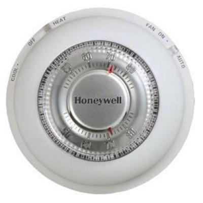
- A more modern version of the T87 thermostat is the T87N seen with the heating-cooling base. This product is advertised as mercury-free because it does not employ a bimetallic strip
- caveats:
- placing a "C" before these part numbers gets you a thermostat with a Celsius scale (used everywhere in the world except the USA)
- Honeywell no longer makes or supports thermostats. They sold the technology to www.resideo.com who markets the stuff under the brand Honeywell Home
(some) Schematic Diagrams and Their Signals
The following schematic diagrams were printed on a sticker pasted to the thermostat base of a THM303A I purchased at RONA (a Canadian big-box store) in 2010. The diagrams below were extracted from page-14 of the (non-copyrighted) associated manual which I am only presenting here for discussion purposes. See the following table for a discussion of the signals.
| Signals | Wire Color (rarely followed) |
Notes (from the web-page editor) |
|---|---|---|
| H1 | this vendor employs this signal to operate a humidifier | |
| H2 | this vendor employs this signal to operate a humidifier | |
| RC | Red | Return-line Cooling (many times this signal is linked to RH) see notes 1-2 below |
| RH | Red | Return-line Heating (many times this signal is linked to RC) see notes 1-2 below |
| W | White | Function: Call for heat (informally speaking, "W" meant "Warming") |
| G | Green | Function: Fan |
| Y | Yellow | Function: Call for cooling |
| O | Orange | In some systems the "O" and "B" signals were used to control the respective dampers. In other systems the "O" signal was used to change the mode from heating to cooling (so "O" meant "B-not") |
| B | Blue (or Brown) | In some systems the "O" and "B" signals were used to control the respective dampers. In other systems the "O" signal was used to change the mode from heating to cooling (so "O" meant "B-not") |
Notes:
- Many times RC and RH are linked together at the thermostat base (but never when two transformers are used as seen in the 5-wire diagram)
- Why are RH and RC known as "return lines"? Inspect this example of
residential electrician wiring
- the so-called "Alternative - California Style" shows raw power is first connected to the load (a light bulb in this case) which early "electrical codes" thought were a little safer since raw power was never sent to the switch.
- as soon as you replace the light switch with a receptacle (outlet) the conventional wiring seems a little more safe (while raw power is going to the switch, powering off the switch totally depowers a "switched receptacle".
CAVEAT: your local "electrical code" always supersedes anything you see on the internet.
Programmable-1
- in my categorization, type-1 programmable thermostats require batteries but also require power (which they steal parasitically) from the heating-cooling control lines. If they did not do this then the batteries would only last 7-10 days.
- These should be able to directly connect to older heating-cooling systems where the small current stolen will not activate a relay (e.g. call for heat).
- These may need an isolation device to connect to newer heating-cooling systems
- here, the relays in the heating-cooling system are so sensitive that the parasitic current drawn by the thermostat would be misinterpreted as a call (e.g. call for heat).
observations-extrapolations
- Think about this for a moment: Each battery generates 1.5 VDC and there are usually 2-4 of them in these thermostats meaning they require somewhere between 3 to 6 VDC.
- The control lines are powered by 24 VAC which means that sampling resistors would need to be connected to one (or more) signal lines.
- The output from this network could then be run into a rectifier (half-wave = cheap implementation; full-wave = better) to convert the AC into DC.
- A clever resistor-network design would also provide the primary voltage drop from 24 (RMS) to the final 3 to 6.
comment: these are commodity devices where every penny counts. If it were not so then the designer would implement a proper switched-mode supply which could produce the exact voltage most efficiently.
Programmable-2
- In my categorization, type-2 programmable thermostats require a direct power connection from the heating-cooling equipment.
- This reason for this is the higher power requirements of putting a real CPU chip (with EEPROM and RAM) into the thermostat to support things like:
- large colored touch screen with back-light.
- Wi-Fi interface (which can also tell your the outside temperature once it knows your postal code after you register it here: https://www.mytotalconnectcomfort.com
- Thermostats like the Honeywell
Home RTH9585WF require an additional connection known as the C-wire. Here is the quote from their
manual
Important! C wire is required and is the power source for your thermostat. Without a C wire, your thermostat will not power up.
and here https://www.honeywellhome.com/us/en/support/everything-you-need-to-know-about-a-c-wire/ - I did not have a C-wire behind my old thermostat so needed to run an additional solid 18-guage wire to my furnace (Rheem/Ruud high-efficiency natural gas) which did have a signal terminal labeled "C". You can buy this stuff at any big-box store but I just bought a package of "thermostat wire" from good old Canadian Tire (another Canadian big-box store)
- I noticed that the RH + RC at the thermostat were connected to "R" at the furnace.
- I used a DVM to prove that "R" at the furnace was one side of the 24 VAC transformer whist "C" was on the other side (so this is raw 24 VAC power)
- comment: "I think" that this terminal was labeled "C" for "common". Why? If you inspect the 4-wire and 5-wire schematics (above) you will notice that this is a common connecting point for the relays.
Links
- NSR's climate science
- NSR's introduction to climate modeling
- Thermostats
- From Wikipedia:
- https://en.wikipedia.org/wiki/Thermostat
- https://en.wikipedia.org/wiki/Thermostat#24_volt_thermostats (chart of common signal names)
- From Wikipedia:
- Residential Electrical Wiring
